Centralizing Front Wing Control: The Integrated Actuator Pylon Innovation
Our engineering team developed the Integrated Actuator Pylon as a revolutionary approach to front wing flap adjustment. Traditionally, actuator units have been housed externally or mounted outboard on the front wing structure, often increasing aerodynamic drag and complexity. To overcome these challenges, we centralized the actuator system within the front wing pylon itself, creating a neatly integrated solution that reduces both aerodynamic interference and weight.
The motivation behind this innovation was to streamline the actuation mechanism, protect the actuator from external debris, and optimize front wing airflow management. Moreover, the design was guided by a demanding regulatory environment that strictly controls geometric constraints, actuator system performance, and structural integrity. Our aim was to maximize flap adjustability while ensuring seamless compliance with FIA technical regulations.
Regulatory Framework and Design Constraints
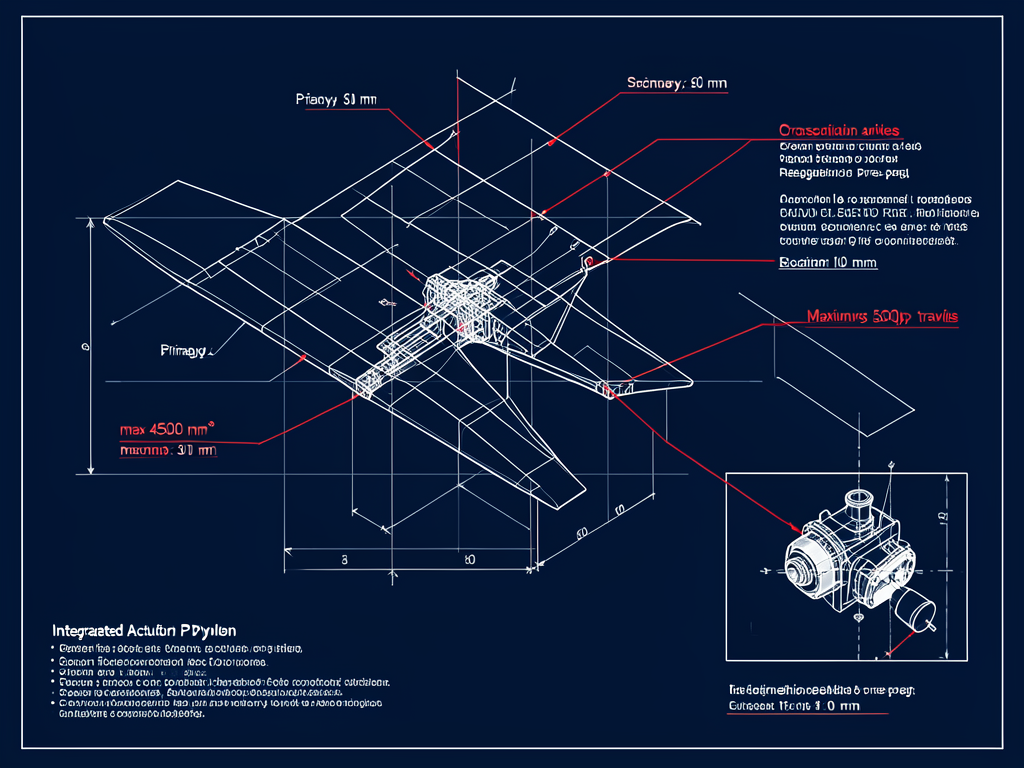
The design of our Integrated Actuator Pylon is heavily influenced by precise FIA regulations. Geometrically, the pylon's cross-sectional area must not exceed 6000 mm² at any Z-plane [1], with a maximum thickness limit of 35 mm in the lateral (Y) direction [2]. These limits require a compact, carefully contoured structure.
The actuator system is specified to be either electromechanical or compact hydraulic, conforming to the requirements outlined in [3] and [4]. The aperture for actuator access, a critical integration point, is restricted to the minimum size necessary to accommodate the swept bounding volume of the Front Wing Straight-Line Mode (FW SLM) linkage plus a 5 mm offset [5]. We carefully engineered this aperture to avoid aerodynamic penalties while enabling full actuator motion.
Structurally, the pylon must maintain deflection limits not exceeding 15 mm under a 1000 N load, safeguarding the rigidity and reliability of the front wing assembly [6]. Additionally, front wing flap travel limits are regulated to maximum deviations of 30 mm for the primary flap and 60 mm for the secondary flap, with actuator transition times between modes capped at 400 ms [7]. Our design choices navigate these intertwined constraints, balancing the regulatory mandates with functional requirements.
Technical Architecture of the Integrated Actuator Pylon
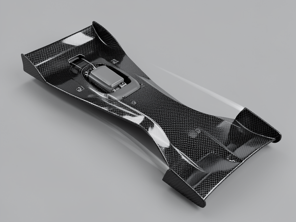
We structured the pylon to serve as both an aerodynamic component and an actuator housing. A hollow cavity within the carbon fiber composite pylon accommodates the actuator, sealed tightly to maintain aerodynamic smoothness and prevent environmental ingress.
We evaluated electromechanical and compact hydraulic actuators, ultimately favoring an electromechanical unit for its precision, compactness, and integration with the FIA Standard ECU. Electromechanical actuation simplifies hydraulic routing and reduces potential leak points, benefiting reliability. However, hydraulic actuators offer high force density and a familiar response profile. The choice was made considering packaging constraints, weight, and integration complexity.
The actuator is connected mechanically to the primary and secondary flaps via robust linkages housed within the pylon volume. This integration maintains a sleek aerodynamic profile that minimizes drag. Internally, the actuation system sits fixed within the pylon's contours, with careful clearance and mounting designed to prevent exceeding the 5 mm aperture offset limit [5].
The entire assembly enables precise flap adjustments across the maximum travel ranges permitted, with fail-safe default positioning to "Corner Mode" in case of system failure, complying with FIA mandates [7].
Manufacturing and Quality Assurance Strategies
Building the Integrated Actuator Pylon required advanced manufacturing techniques. We used high-strength carbon fiber pre-preg composite layups with tailored fiber orientations to optimize the strength-to-weight ratio and dimensional stability, cured precisely under autoclave conditions.
Dimensional accuracy was guaranteed through high-resolution 3D scanning of each manufactured part, verifying critical areas such as aerodynamic surface continuity, cross-sectional compliance [1][2], and the actuator access aperture geometry [5].
Sealing around the actuator access aperture employed flexible, aerodynamic seals to prevent air leakage and protect from dirt and moisture. Access panels were designed for quick removal and secure closure, facilitating maintenance without compromising aerodynamic integrity.
Durability was assessed through rigorous cycling tests of the actuator system, verifying smooth operation within travel limits and fail-safe response under repeated actuation cycles.
Structural and Functional Validation
We validated the structural integrity through detailed finite element analysis (FEA), confirming that the pylon withstands the 1000 N load with under 15 mm deflection as mandated [6]. These simulations guided reinforcement placement and material thickness optimization.
Physical load tests complemented FEA predictions, applying symmetrical and asymmetrical forces at specified points while precisely measuring deflection using laser scanning tools. Our results consistently met the deflection limits with margins for operational safety.
Functional testing focused on actuator performance: verifying the maximum flap travel of 30 mm (primary) and 60 mm (secondary) [7], transition times under 400 ms between corner and straight-line modes, and correct fail-safe defaulting to corner mode upon simulated system faults. These tests assure reliability and regulatory compliance.
Failure Modes and Risk Mitigation
We identified several potential failure modes during development. Mechanical failure of the actuator remains the highest risk; to mitigate this, we selected actuators with proven high cycle life and integrated redundant fail-safe systems ensuring a reliable return to "Corner Mode" should faults arise [7]. Routine inspection protocols and predictive maintenance are recommended to preempt failures.
Structural issues like stress concentration around the internal actuator housing were addressed via FEA and by adding load-spreading features at actuator mount points, ensuring the pylon's strength complies with geometric and flexibility limits [1][6].
We meticulously designed the actuator access aperture to avoid exceeding regulatory dimension limits, reducing aerodynamic penalties and ingress risks. Flexible seals prevent contamination and wear-induced leaks, while tight manufacturing tolerances maintain dimensional control [5].
Fail-safe mechanism robustness was a priority, employing redundant subsystems tested extensively under simulated fault conditions to guarantee regulatory compliance and on-track safety.
Performance Impact and Aerodynamic Benefits
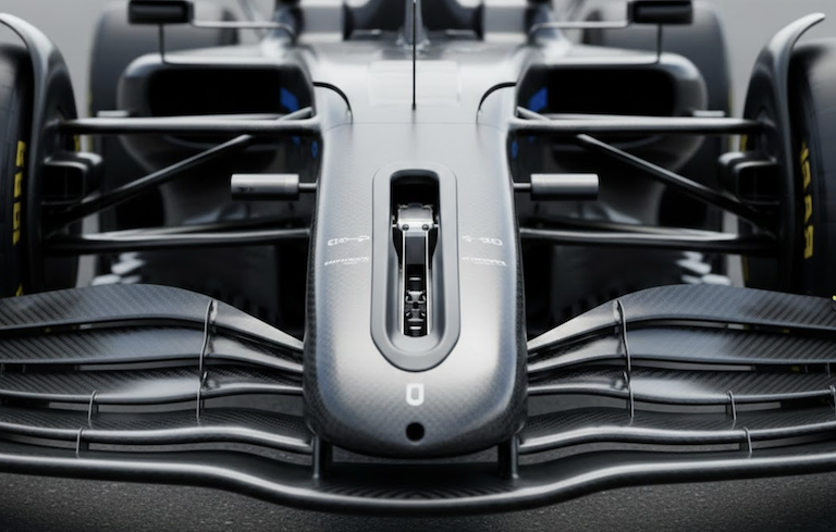
Centralizing the actuator within the pylon brings significant aerodynamic advantages. By removing bulky outboard actuator housings, we reduced drag-inducing protrusions on the front wing assembly, streamlining airflow and enhancing downforce consistency.
Weight savings arise from consolidating hydraulic lines or wiring centrally, avoiding duplicated systems across both pylons. This reduction contributes to overall vehicle mass optimization and improved weight distribution.
This integration also allows more precise and faster front wing flap adjustments, benefiting dynamic aerodynamic balance during cornering and straight-line speeds. The actuator's embedment reduces aerodynamic disturbances, potentially enabling more aggressive flap angles within the permitted travel range [7].
The overall outcome is a more efficient and responsive front wing system capable of fine aerodynamic tuning with minimized drag and weight penalties.
Conclusion and Future Development Considerations
Our Integrated Actuator Pylon design marks a significant step forward in front wing actuation systems. By marrying regulatory compliance with innovative aerodynamic integration and mechanical design, we demonstrated that a centralized actuator system within the pylon is both feasible and advantageous.
This approach balances strict deflection and geometric constraints with performance gains in drag reduction and weight savings. It also enhances reliability through simpler actuating systems and robust fail-safe behavior.
Looking ahead, this architecture sets a new benchmark for integrating active aerodynamic components. Future developments may leverage advanced materials and miniaturized actuators further to refine response times and packaging efficiency, potentially extending this centralized concept across other aerodynamic assemblies.
References
- [1]: FIA 2026 Technical Regulations - Article C3.10.7.b.i
- [2]: FIA 2026 Technical Regulations - Article C3.10.7.b.ii
- [3]: FIA 2026 Technical Regulations - Article C5.11.3
- [4]: FIA 2026 Technical Regulations - Article C5.11.4
- [5]: FIA 2026 Technical Regulations - Article C3.16.3
- [6]: FIA 2026 Technical Regulations - Article C3.18.2
- [7]: FIA 2026 Technical Regulations - Article C3.10.10