The Dual-Curvature Front Wing Outboard Footplate: Pushing Aerodynamic Boundaries Within Regulations
The relentless pursuit of aerodynamic efficiency in Formula 1 demands innovation that navigates the intricate web of technical regulations. Among the many components contributing to a car's aerodynamic performance, the front wing's outboard footplate plays a critical role in managing airflow at the wing's extremities. This article delves into the sophisticated design of the Dual-Curvature Front Wing Outboard Footplate, a component engineered to maximize performance while meticulously adhering to the FIA's technical mandates, specifically Article C3.10.3.
Understanding the Regulatory Landscape: Article C3.10.3
The design and implementation of the front wing outboard footplate are governed by a strict set of regulations, primarily detailed in Article C3.10.3 of the Formula 1 technical regulations. These rules define both the permissible design freedoms and the critical boundaries that must not be breached:
- RV-FWEP-OFP Envelope (C3.10.3 (a)): The footplate must reside entirely within a precisely defined three-dimensional volume known as the RV-FWEP-OFP envelope. This crucial constraint ensures that the component's overall dimensions, placement, and any associated features do not extend beyond prescribed limits, preventing overly complex or expansive designs that could lead to uncontrolled aerodynamic effects.
- Two-Section Constraint (C3.10.3 (c)): Rearwards of a specific longitudinal plane, defined as XF = -425mm, the cross-section of the footplate, when viewed in a plane parallel to the car's longitudinal axis (X-Plane), can exhibit at most two distinct sections. This regulation shapes how compound curves and changes in profile can be utilized to manage airflow effectively.
- Convex Radii of Curvature (C3.10.3 (d)): To prevent detrimental flow separation and maintain aerodynamic efficiency, any convex curvature applied to the footplate must possess a minimum radius of 5mm. This requirement directly influences the smoothness and effectiveness of the airflow interacting with the component's surface.
These regulations, while restrictive, provide a structured framework within which innovative aerodynamic solutions can be developed. The Dual-Curvature Front Wing Outboard Footplate stands as a testament to how teams strategically leverage these rules to achieve a competitive advantage.
The Dual-Curvature Philosophy: Optimizing Flow with Complexity
The core innovation of this footplate lies in its sophisticated dual-curvature profile. Unlike a simpler, single-radius design, this component deliberately incorporates two distinct curves at different longitudinal positions. This sophisticated approach is directly enabled by the two-section constraint stipulated in Article C3.10.3 (c). A single-curvature footplate, while compliant, would offer a less optimized solution for managing airflow across its entire span and length. The dual-curvature strategy allows for a more nuanced control of the airflow, critical for maximizing downforce and minimizing drag.
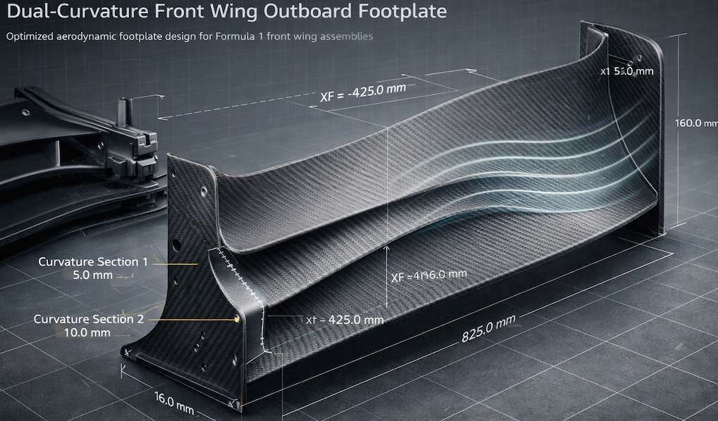
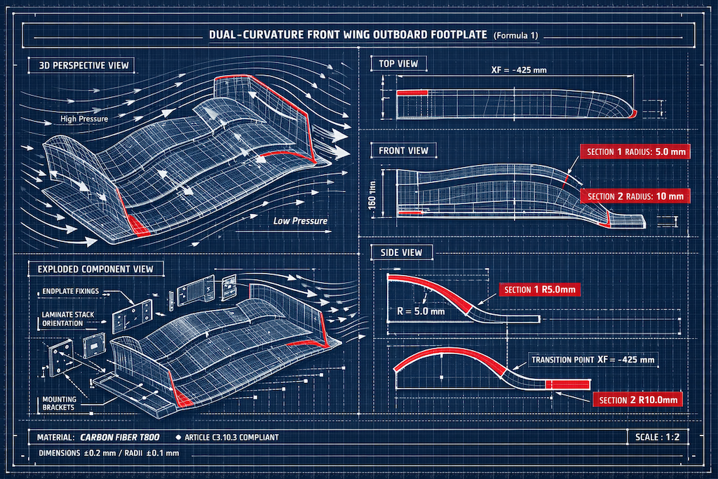
The transition between these two distinct curvature sections occurs precisely at the regulatory boundary of XF = -425mm. The forward section, adhering to the minimum requirement of Article C3.10.3 (d), features a convex radius of curvature of 5mm. This ensures compliance while initiating a controlled interaction with the oncoming airflow, energizing it close to the surface. As the airflow moves rearwards beyond XF = -425mm, the footplate transitions to a second curvature section. This aft section boasts a more generous 10mm radius, optimized for enhanced flow reattachment and energy recovery. This deliberate use of differing radii is a sophisticated aerodynamic strategy: the 5mm radius in the forward section helps to energize the airflow, while the larger 10mm radius in the aft section is optimized for flow re-energizing and mitigating separation, aiming to maximize downforce generation in the outboard region of the front wing.
Design Parameters and Regulatory Adherence
The effectiveness of the Dual-Curvature Front Wing Outboard Footplate is underpinned by a precise set of design parameters, all meticulously calibrated within the bounds set by Article C3.10.3 and related regulations:
- Curvature Radii: The footplate features a 5mm radius section (mandated by C3.10.3 (d)) and a 10mm radius section. The transition point is fixed at XF = -425mm, strictly adhering to the two-section constraint (C3.10.3 (c)).
- Dimensions: The footplate is engineered with a height of 160mm and a width of 825mm. These dimensions are carefully chosen to optimize aerodynamic performance while remaining within the overall front wing regulations and the specific RV-FWEP-OFP envelope defined in Article C3.10.3 (a). The height is further constrained by Article C3.10.1 (g), and the width by Article C3.10.3 (a).
- Material and Surface Finish: Manufactured from high-strength carbon fiber (T800), the footplate offers an excellent strength-to-weight ratio, crucial for performance F1 components (Article C3.18.2). A critical aspect for aerodynamic efficiency is the surface roughness, meticulously controlled to a maximum of 1.5 µm. This adherence to a smooth surface minimizes drag and ensures predictable airflow behavior, as also emphasized in manufacturing notes and engineering checks (C3.10.3 (a)).
- Structural Integrity: The component is designed to withstand significant aerodynamic loads, validated to handle up to 7000 N without deformation or failure (Article C3.18.2). This robustness is essential to prevent catastrophic failure under the extreme forces experienced during racing.
Engineering, Validation, and Failure Mode Mitigation
Achieving regulatory compliance and optimal performance necessitates rigorous engineering and validation processes, with a keen eye on potential failure modes:
- CFD (Computational Fluid Dynamics) Simulations: These simulations are indispensable for predicting and optimizing airflow behavior around the complex dual-curvature profile. They guide the design to maximize downforce and minimize drag, ensuring the design intent is met while anticipating potential issues like flow separation due to improper curvature transitions.
- Wind Tunnel Testing: Physical validation in wind tunnels confirms CFD predictions and identifies real-world aerodynamic nuances. This stage is crucial for verifying the design's effectiveness and ensuring it operates as intended under dynamic conditions.
- Manufacturing Precision: The use of carbon fiber prepreg with a T800 fiber and epoxy resin matrix demands precise manufacturing. Machining edge radii to a tolerance of ±0.2 mm and achieving surface finishes of Ra ≤ 1.0 µm are vital for aerodynamic integrity and preventing flow separation. Non-destructive testing (NDT) ensures the structural integrity of the composite, mitigating risks of structural failure under load.
- Detailed Metrology and Compliance Checks: The engineering tests detail a comprehensive metrology plan. This involves using Coordinate Measuring Machines (CMMs), laser height gauges, and profilometers to meticulously verify dimensions, curvature radii, surface roughness, and interface integrity against regulatory requirements. This rigorous verification is essential for defending compliance during technical scrutineering and ensuring that risks such as regulatory non-compliance due to curvature violations or manufacturing defects leading to surface roughness issues are preemptively addressed. Structural load testing further validates that the footplate can withstand the specified loads without deformation, directly countering the structural failure mode.
Aerodynamic Impact and Competitive Advantage
The Dual-Curvature Front Wing Outboard Footplate is more than just a compliant component; it represents a strategic aerodynamic advantage. By expertly navigating the constraints of Article C3.10.3—particularly the two-section rule and the minimum radius requirement—this design pushes the boundaries of aerodynamic efficiency.
The careful management of airflow at the front wing's extremities is fundamental to the overall balance and performance of the car. Optimized airflow over the footplate contributes significantly to:
- Increased Downforce: Enhancing the downforce generated by the front wing, especially critical for higher cornering speeds.
- Improved Stability: Contributing to better straight-line stability and more predictable vehicle dynamics under braking.
- Drag Reduction: Minimizing drag is crucial for maintaining top speeds on straights and improving overall lap times.
- Outwash Effect: Effectively directing airflow around the front tires can help create a cleaner aerodynamic wake for the rest of the car, benefiting overall aerodynamic efficiency.
Conclusion
The Dual-Curvature Front Wing Outboard Footplate exemplifies the intricate synergy between deep engineering insight and strict regulatory adherence that defines modern Formula 1. It showcases how a thorough understanding of aerodynamic principles, coupled with meticulous attention to the FIA's technical rules, can unlock significant performance gains. By strategically leveraging the specific allowances within Article C3.10.3, teams can design components that not only comply but also push the performance envelope, providing a crucial competitive edge. The successful validation, confirmed through rigorous CFD, wind tunnel testing, and detailed metrology, ensures that this advanced aerodynamic solution is both effective on track and fully compliant with the sport's demanding regulations.