Snap-Through Dynamics: Engineering the Functional Failure Hinge in F1 Front Wings
Introduction to Adaptive Front Wing Hangers
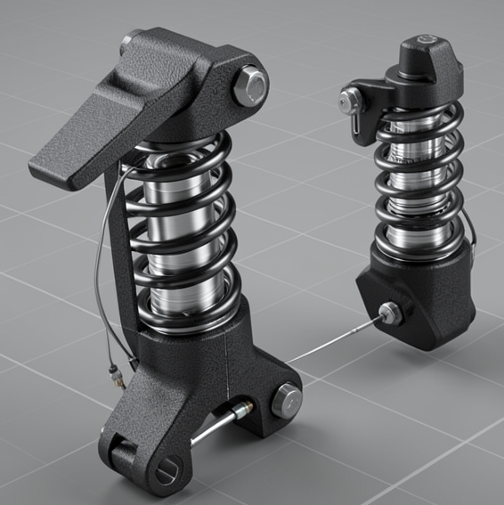
The Functional Failure Pressure-Relief Hanger is an innovative structural component integrated into the front wing suspension system. Positioned at the critical interface between flap elements and the chassis nose, it plays a pivotal role in balancing the aerodynamic demands for downforce and the mechanical rigidity necessary for precision handling. This adaptive hanger maintains a rigid configuration during cornering, preserving optimal front wing incidence, yet it passively transitions under certain aerodynamic loads to alter flap angle and improve high-speed performance.

Mechanical Design and Materials
At the heart of this system lies a bi-stable buckling strut mechanism—an elegantly simple yet robust structure that allows the hanger to snap between two distinct mechanical orientations. When aerodynamic loads remain below the design threshold, the strut upholds a rigid form, ensuring no unwanted deflections influence wing incidence. Upon exceeding this threshold, the pre-buckled strut collapses, enabling a controlled change in the wing’s angle.
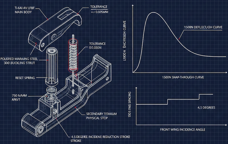
To reset the mechanism automatically, a high-rate coil spring provides sufficient restoring force, promoting a passive return to the original mode as aerodynamic loads decrease. Material selection is critical: the buckling element is manufactured from Maraging Steel, prized for its exceptional fatigue life and predictable yield characteristics, while the main hanger body leverages the lightweight strength of Ti-6Al-4V titanium alloy produced through advanced laser powder bed fusion techniques. Achieving reliable performance demands tight manufacturing precision to maintain the delicate balance between rigidity and controlled flexibility.
Load-Triggered Snap-Through Behavior
This adaptive hinge is calibrated to trigger snap-through when the aerodynamic load on the front axle surpasses approximately 1450N. This load threshold typically corresponds to maximum velocity phases on long straights. When triggered, the buckling strut yields, allowing the flap to reduce its incidence angle by about 5 degrees. This subtle but impactful change sheds aerodynamic drag and shifts the aerodynamic balance rearwards, reducing the potential for high-speed front-end porpoising and enhancing top-end speed.
Critically, a secondary titanium physical stop limits the flap’s movement to remain within the strictly regulated RV-FW-PROFILES volume, ensuring compliance even during the snapped state. When the car brakes and aerodynamic forces diminish, the mechanical spring overcomes the reduced load, driving a passive reset of the strut and restoring the wing to its high-incidence "Corner Mode." The result is a seamless, purely mechanical adaptation tuned to track conditions without electronic intervention.
Regulatory Compliance and Static Load Testing
Meeting FIA regulations forms the backbone of this system’s design validation. The hanger must demonstrate near-absolute rigidity under a 60N static load test as required by Article C3.18.3, ensuring no measurable deformation compromises aerodynamic stability during cornering. In addition, spacing between adjacent hangers strictly adheres to the 150mm minimum set by Article C3.10.11.b, guaranteeing structural integrity and proper force distribution.
To comply with the flap volume constraints outlined in Article C3.10.10.u, the hinge motion is physically limited by designed stops that prevent any excursion beyond the permissible aerodynamic profiles. Verification combines precision 3D scanning and mechanical measurements, while cyclic testing confirms the system’s durability and regulatory alignment. This approach ensures the passive aero-elastic behavior is both effective and fully legal.
Failure Modes and Mitigations
Several challenges arise in the design and operation of this passive hinge system. One risk is failure to reset, where friction or contamination could inhibit the coil spring’s ability to restore the original flap incidence. To mitigate this, critical sliding surfaces are coated with low-friction diamond-like carbon (DLC), reducing wear and hysteresis.
Fatigue of the buckling element over repeated cycling can lower the trigger load threshold unpredictably. Addressing this involves rigorous cyclic load testing and implementing replacement intervals around 500km to maintain performance consistency. Finally, the rapid incidence change poses a risk of aerodynamic stall or flow separation; transition timing has been carefully damped at around 400ms to smooth the incidence shift, stabilizing airflow and preserving downforce.
Sensor Integration and Monitoring
Our system integrates high-speed linear variable differential transformer (LVDT) sensors linked directly to the FIA-standard ECU. These sensors provide real-time position feedback of the hinge, enabling engineers and stewards to monitor the precise moment and duration of mode transitions throughout a race.
This sensor data is critical to ensuring that the passive transitions operate within the expected parameters, verifying mechanical function without electronic control. Such monitoring also supports compliance with FIA telemetry standards, providing transparent operation validation.
Assembly Interfaces and Installation Accuracy
The Functional Failure Pressure-Relief Hanger mounts rigidly to the primary flap spar via dual M8 high-tensile fasteners, ensuring a robust load path between the flap and the chassis. The integration includes a structural interface for the front wing adjuster fairing, designed and positioned to meet aerodynamic and regulatory visibility requirements.
Accurate installation is paramount: well-controlled hanger spacing avoids compromising the bi-stable mechanism or inducing unintended aerodynamic effects. Installation precision is verified by coordinate measurement techniques during assembly to uphold the mandated 150mm minimum spacing and ensure repeatable mechanical performance.
Operational Dynamics: Transition Timing and Aerodynamic Impact
The snap-through transition is engineered to occur in response to specific aerodynamic loads encountered at high speeds, balancing stiffness during cornering with flexibility on straights. The mechanical reset spring defines the system’s recovery time constant, calibrated to approximately 350–400 milliseconds to ensure the wing returns to Corner Mode swiftly as aerodynamic pressure drops.
This timing is a key factor in maintaining predictable car behavior, avoiding abrupt aerodynamic shifts that could unsettle the chassis. The combination of bi-stable mechanics and spring dynamics creates a reliable, passive aero-elastic system that enhances both speed and stability through the race.
Conclusion: Innovation in Passive Aero-Elastic Control
The Functional Failure Pressure-Relief Hanger exemplifies how passive mechanical design can be leveraged within the framework of FIA regulations to deliver tangible aerodynamic advantages. By strategically exploiting bi-stable buckling mechanics, precision materials engineering, and carefully calibrated load thresholds, we have created a front wing interface that dynamically adapts without active electronic control.
This innovative integration enhances drag reduction and aerodynamic balance during high-speed phases while preserving the rigidity and downforce vital for cornering performance. The system’s reliability and compliance underscore its potential as a cornerstone in the evolving landscape of F1 aerodynamic innovation.
References
- Article C3.18.3: FIA 2026 Technical Regulations - Article C3.18.3
- Article C3.10.11.b: FIA 2026 Technical Regulations - Article C3.10.11.b
- Article C3.10.10.u: FIA 2026 Technical Regulations - Article C3.10.10.u
- Article C3.10.10.v: FIA 2026 Technical Regulations - Article C3.10.10.v
- Article C3.2.2.a: FIA 2026 Technical Regulations - Article C3.2.2.a