Skeletonized Web Architecture: Engineering the Forward Survival Cell Extension
Introduction to the Skeletonized Chassis Web
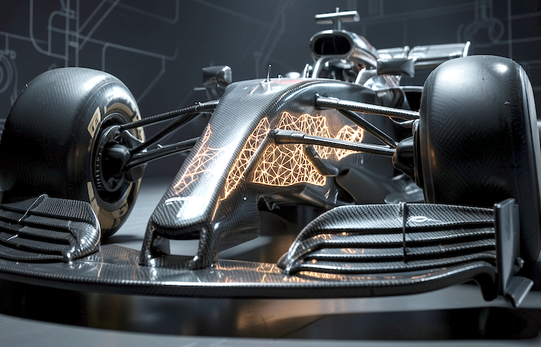
The forward upper section of a Formula 1 car's survival cell plays a crucial role in driver protection and chassis integrity. Traditionally, this area consists of a solid upper chassis panel closing off the driver's compartment frontwards, ensuring robust structural continuity. Recently, a novel approach has emerged involving the skeletonization of this solid panel into discrete vertical webs. This design innovation leverages the allowances in the FIA 2026 Technical Regulations, specifically Article C12.2.2.f.ii, which permits selective second-stage material removal within the survival cell structure.
By transitioning to two vertical webs instead of a solid panel, the chassis retains the mandated structural width while opening an internal cavity. This cavity, forward of the dash bulkhead, introduces new functional possibilities for ballast positioning and cooling management. The modular removable section rule under Article C12.2.2.g.iv further enables this architecture to be designed as a detachable unit, affording flexibility in setup and maintenance.
This article explores the engineering principles, material choices, manufacturing methods, and regulatory considerations underpinning this skeletonized chassis web extension.
Structural Design and Geometry Constraints
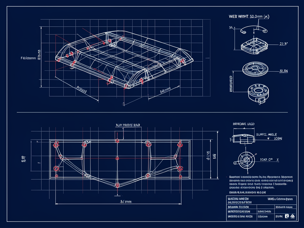
The skeletonized chassis web must satisfy stringent geometric criteria mandated by the regulations to ensure performance and safety. The visible structural surfaces, defined relative to the car's X-axis (longitudinal axis), are restricted to a maximum surface normal angle of 25 degrees relative to the X-plane [Article C12.2.2.g.iii]. This limitation controls the aerodynamic profile and maintains FIA compliance.
Structural heights are governed by a minimum 250mm vertical clearance above the Z-plane in all cross-sections forward of XC=-1600 [Article C12.2.2.f.ii]. This ensures sufficient robustness of the survival cell structure beneath the skeletonized section. The vertical structural webs are precisely 50mm wide each, summing to the mandatory 100mm cumulative structural width across every X-plane, as required by the same article.
The webs form continuous load paths extending from the Front Impact Structure (FIS) interface at the vehicle nose (XA=0) back to the survival cell bulkhead positioned at XC=-1600. Maintaining these load paths ensures crashworthiness and stiffness continuity, integral to driver safety. The discontinuous panel is thus carefully engineered as two I-beam-like vertical webs maintaining rigidity and load transfer.
Material Selection and Manufacturing Techniques
High-performance composite materials are vital to optimize strength-to-weight ratios in this structure. The skeletonized webs use ultra-high modulus carbon fiber prepreg, such as M46J or K139 fibers, chosen for their exceptional stiffness characteristics and fatigue strength. The primary fiber orientation is a 0/90-degree layup dominant in the vertical X-Z plane, aligning fiber direction with the main load axes and resistance to buckling under aerodynamic compression.
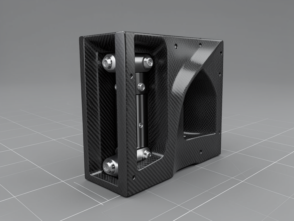
To facilitate the mounting of tungsten ballast, the structure integrates bonded aluminum 7075-T6 hardpoints. These hardpoints are fixed to ensure the ballast remains permanently mounted during race sessions, meeting the regulations for ballast security.
Manufacturing tolerances are tightly controlled, with ±0.5mm allowed at the XA=0 interface to maintain the 7mm maximum periphery offset with the FIS, preventing aerodynamic penalties or regulatory infringements [Article C12.2.2.h]. The combination of precise carbon layup, hardpoint bonding, and tolerance management results in a lightweight yet robust structural component.
Innovative Internal Ballast and Cooling Bay
A key innovation of the skeletonized design is the creation of a large internal cavity—the Internal Ballast and Cooling Bay—formed in the central volume vacated by the removed material. This cavity provides dual functionality essential for performance optimization.
Primarily, it accommodates low-slung tungsten ballast positioned to lower the car's center of gravity (CoG) and optimize polar moment of inertia. Such positioning improves front-end mechanical grip and overall handling by concentrating mass close to the car's longitudinal axis and low in the chassis.
Simultaneously, this volume functions as the termination point for the chassis cooling air influx governed by Article C3.16.19. Forward cooling air enters through ducting channels integrated into the survival cell upper section and is channeled to this internal volume. Here, high-energy boundary layer air is conditioned and pre-cooled, assisting thermal management of electronic systems before the air progresses into the cockpit area. The sealed internal ducting path mitigates unwanted hot air bypass, contributing both to driver comfort and component reliability.
Modularity and Mechanical Fastening Solutions
The skeletonized web assembly is designed as a removable structural unit in accordance with Article C12.2.2.g.iv. This permits mechanical fastening solutions instead of permanent bonding, provided the joints withstand a verified load of at least 50kN in longitudinal and vertical directions.
Titanium grade 12.9 fasteners, combined with oversized helicoil inserts embedded in the carbon substrate, form the primary fastening system. This robust fixing ensures fastener shear resistance and maintains structural integrity while enabling modularity. The ability to remove and reinstall the web unit rapidly permits quick ballast adjustments and cooling configuration changes without necessitating a full chassis re-homologation process.
This modular approach offers strategic advantages in race weekend preparations by allowing flexible setup alterations aligned with track demands or evolving aerodynamic strategies.
Failure Modes and Mitigation Strategies
Several potential failure modes are mitigated through careful engineering:
- Fastener Shear: The mechanical joints are designed to handle shear loads up to 50kN, using redundant titanium fasteners and helicoil reinforcements to avoid premature failure.
- Web Buckling: Vertical carbon fiber orientation and use of ultra-high modulus materials prevent buckling of the narrow webs under high aerodynamic downforce, maintaining structural stiffness.
- Seal Failure: The cooling air termination point risks hot air bypass into the cockpit. This is prevented by employing high-temperature silicone pressure bulb seals that ensure airtight ducting.
- Manufacturing Tolerance Stack-ups: Precision assembly techniques control dimensional variation so the cumulative web width and interface gaps remain within regulatory limits.
These mitigations collectively ensure the structure's reliability and compliance throughout the demanding conditions of F1 racing.
Regulatory Compliance and Validation Testing
Compliance with regulations is demonstrated through seven rigorous checks:
- Structural Width Verification: Laser scanning confirms that the cumulative web widths consistently meet the 100mm minimum across all X-planes, as specified in Articles C12.2.2.f.ii and C12.2.2.g.ii.
- FIS Interface Precision: Coordinate measuring machine (CMM) surveys validate that the periphery gap to the Front Impact Structure does not exceed 7mm, aligning with Article C12.2.2.h.
- Surface Normals Constraint: Digital analysis maps prove that all visible surfaces from the front maintain a surface normal angle under 25 degrees, per Article C12.2.2.g.iii, ensuring aerodynamic legality.
- Fastener Load Capacity: Finite element analysis (FEA) and structural calculations certify fasteners resist the required 50kN load per Article C12.2.2.g.iv.
- Structural Height Compliance: 3D dimensional measurements demonstrate the 250mm minimum structural height is maintained above the Z-plane throughout the forward section, in line with Article C12.2.2.f.ii.
- Cooling Air Path Pressure Tests: Leak and smoke tests verify sealed internal airflow paths within the ballast bay terminate appropriately without air escaping externally, satisfying Article C3.16.19.
- Suspension Clearance: Geometry sweeps confirm the structural webs extend higher than suspension components at full travel, fulfilling Article C12.2.2.g.v.
These exhaustive tests ensure the skeletonized web meets all performance, safety, and regulatory demands before homologation.
Conclusion and Technical Impact
The skeletonized web architecture represents a significant advancement in survival cell engineering—integrating structural optimization, modular construction, and multifunctional internal volume within FIA constraints. By replacing a solid chassis panel with discrete vertical webs, the design achieves weight savings and structural efficiency while creating a valuable internal cavity for ballast and cooling integration.
This approach enhances chassis flexibility, offering operational advantages without compromising crash safety or aerodynamic integrity. The modular removable unit concept further empowers teams to tailor the front-end setup swiftly across race events. Collectively, these innovations embody the evolution of survival cell design, harmonizing strict regulations with competitive performance enhancements.
As F1 chassis technology progresses, such skeletonized web architectures may catalyze new ways to blend structural function and environmental control, underscoring the multidisciplinary nature of modern racecar engineering.
References
[Article C12.2.2.f.ii]
[Article C12.2.2.g.ii]
[Article C12.2.2.g.iii]
[Article C12.2.2.g.iv]
[Article C12.2.2.g.v]
[Article C12.2.2.h]
[Article C3.16.19]