Modal Downwash Generator Sixth Member: Engineering a Dynamic Aero Suspension Link
Introduction to the Sixth Suspension Member and Modal Downwash Concept
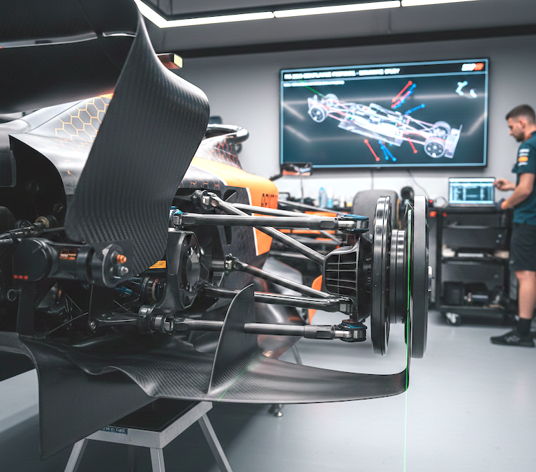
Within the tightly regulated world of Formula 1 rear suspension design, our team engineered a specialized component known as the Modal Downwash Generator (MDG) sixth member. This element is a critical part of the rear suspension architecture, mandated to be exactly six members per wheel according to FIA regulations [1]. What distinguishes the MDG is its exploitation of a key aerodynamic exemption under Article C10.3.6.d, permitting one of these members to feature a non-constant aerodynamic profile—a break from the typical requirement for constant cross-sections and linear shapes.
The concept of modal downwash involves dynamically altering the airflow around the rear suspension to optimize aerodynamic performance. The MDG acts as a passive flow conditioner, leveraging vertical suspension movement to induce a controlled shift in wing profile incidence, thereby modulating rear wing and floor airflow for enhanced downforce. This dynamic behavior taps into a precise exemption that allows the structural member to operate with a cambered, non-uniform airfoil shape, diverging from traditional suspension elements [1].
Design and Technical Specifications of the Modal Downwash Generator
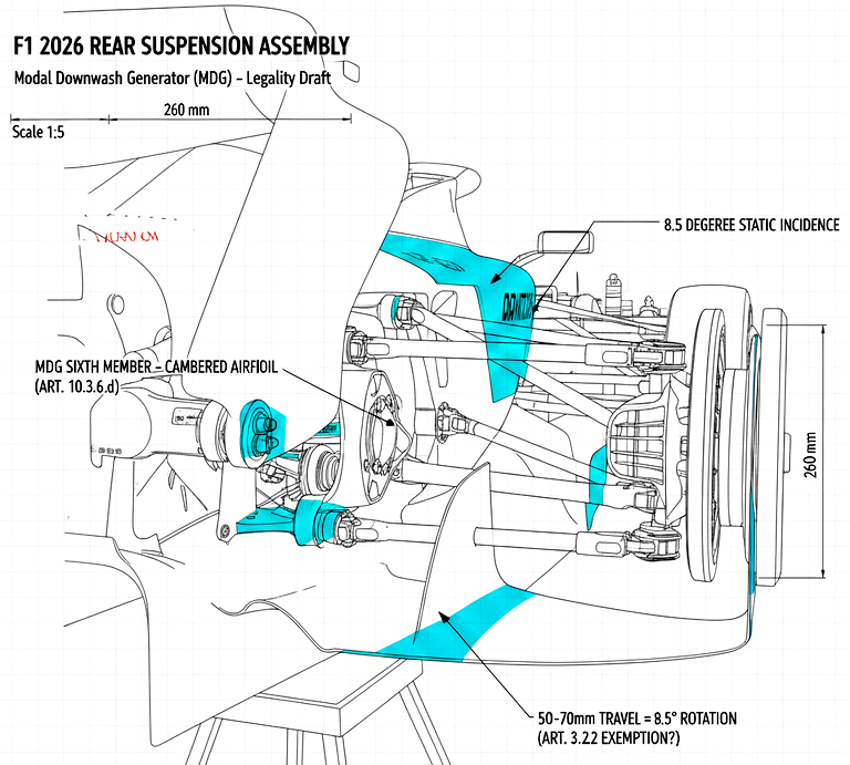
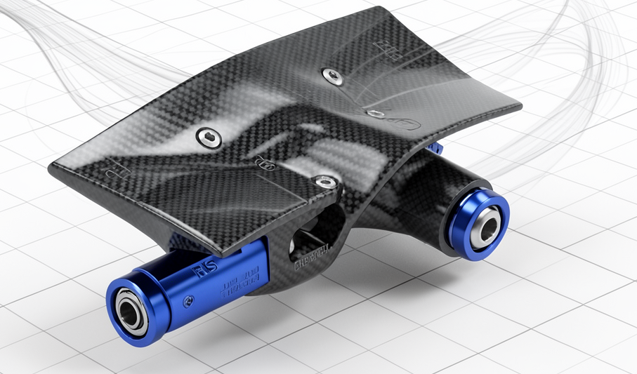
Our design philosophy for the MDG combined structural integrity with aerodynamic sophistication. The member features a cambered wing profile, deliberately crafted with a non-constant chord length tapering from an inboard root chord of 260 mm down to an outboard tip chord of 185 mm. This tapering underpins the aerodynamic shaping needed to influence flow characteristics around the rear wing beam. The aerodynamic profile itself is categorized as a cambered high-lift airfoil, a choice enabled exclusively by the Article C10.3.6.d exemption [1].
Structurally, the MDG incorporates a high-modulus carbon fiber core—using fibers with a modulus of approximately 750 GPa, such as T1000 equivalent—to meet stiffness requirements while minimizing weight. This core is responsible for carrying kinematic loads transferred between suspension pick points. Rigidly bonded to the core is the aerodynamic fairing, co-cured or bonded to a tolerance of ±0.1 mm, ensuring minimal deformation and preserving flow repeatability on track. The overall aspect ratio is kept below 3.5:1 to satisfy regulation limits on aerodynamic fairings [1].
The fairing attachment is critical; it must be fixed with zero relative degrees of freedom to the structural core to ensure the member behaves as a single rigid entity aero-structurally, as stipulated by regulation C3.17.2.b [1]. This monocoque integration preserves the geometric fidelity of the morphing profile through all suspension travel states.
Kinematics and Dynamic Incidence Shifts During Suspension Travel
The core innovation of the MDG lies in its passive kinematic coupling between the Rear Impact Structure (RIS)—the rear crash structure that also serves as an attachment volume—and the rear upright assembly. This linkage arrangement ensures that as the suspension compresses during cornering loads (typically within a 50 mm to 70 mm vertical travel window), the MDG undergoes an active incidence rotation of about 8.5 degrees.
At low-speed or straight-line running, the profile incidence is maintained near neutral (about 5.5 degrees static nose-down), minimizing drag. However, under modal compression, the unique multi-link geometry acts to 'snap' the angle of attack, significantly boosting the downwash effect on the rear wing lower beam. This shift improves flow attachment on the beam wing and enhances rear floor extraction by accelerating airflow under the rear wing section, thus raising total rear downforce [1].
Our 4-post rig tests confirm the incidence angle varies as a unique and repeatable function of vertical suspension travel, with no hysteresis or active actuation—aligning precisely with regulatory demands on movable aerodynamic devices [1].
Regulatory Constraints and Compliance Strategy
The MDG design had to rigorously address multiple FIA regulatory constraints to ensure legality. Firstly, the rear suspension must have exactly six members as defined by Article C10.3.2, with only one member—the MDG—allowed to deviate from constant cross-section rules under C10.3.6.d. Secondly, the incidence of this member at the legality setup must remain within ±10 degrees, per C3.17.3.e, a requirement met by precise assembly and shim calibration.
The fairing’s rigid attachment to the structural core is mandated by C3.17.2.b, disallowing any relative movement between aerodynamic and structural elements. We utilized mathematical kinematic modeling to demonstrate the unique one-to-one mapping of suspension vertical travel to member incidence angle, satisfying C10.3.1’s definition of reasonable compliance and preventing the classification of the MDG as an illegal active aero device.
Our compliance strategy involved extensive CAD documentation, multi-axis tolerance stack analysis, and submission of kinematic derivations to the FIA Technical Delegate. This pre-emptive regulatory collaboration was essential to withstand scrutiny, especially concerning the exemption’s interpretation around asymmetric and dynamic aero profiles [1].
Manufacturing and Quality Control Considerations
The MDG’s manufacturing process is optimized for precision and reliability. The carbon fiber structural core is produced from high-modulus pre-preg material, laid up and cured under strict quality controls to achieve the targeted 750 GPa modulus while ensuring dimensional stability.
The aerodynamic fairing is either co-cured or secondary bonded to the core with meticulous tolerance control within ±0.1 mm, confirmed through 3D scanning and surface metrology. Low-friction needle bearings in the dual pivot joints guarantee smooth, friction-minimal modal shifts during suspension travel without inducing hysteresis.
Assembly is verified on a precision 4-post rig, mapping the angle of incidence against suspension displacement with high-resolution inclinometers. This testing confirms the functional performance aligns with the CAD legality setup and ensures the component maintains its aero and load-bearing roles under track conditions [1].
Failure Modes, Risks, and Mitigation Measures
We identified key failure risks and engineered mitigating solutions. Kinematic singularities, where linkage binding could occur near maximum suspension travel, are addressed through integrated hard-stop bump rubbers on secondary load paths.
Fairing delamination risk from high-pressure gradients at speeds above 300 kph is countered by internal ribbing structures and vacuum-bonded structural adhesives to maintain monolithic integrity. Anticipating FIA legality challenges, we prepared comprehensive CAD motion studies and mathematically derived linkage loci to demonstrate compliance and defend against functional uniqueness disputes [1].
Integration with Rear Wing and Overall Aerodynamic Impact
The MDG’s aerodynamic output is precisely tailored to optimize the wake interaction with the Rear Wing Lower Beam (beam wing). The timed incidence shift dynamically shapes the downwash flow, reinforcing the beam wing’s flow attachment and enhancing the energetic extraction of underfloor airflow.
This integration forms a critical node in the car’s overall aerodynamic package, maximizing rear downforce efficiency without compromising the structural requirements of the rear suspension. Our passive modal control system delivers a blend of aerodynamic gains that translate directly into improved cornering stability and rear-end balance, a decisive competitive edge on track [1].
References:
[1] FIA 2026 Technical Regulations - Articles C10.3.6.d, C3.17.2.b, C3.17.3.e, C10.3.1, C10.3.2, C3.17.3.c, C3.17.3.d